1. The Geometry Engine Problem: Why 7-Digit Coordinates Break CAD
Almost every architectural technician in New Zealand has run into this issue: you receive a high-resolution drone point cloud (.LAZ, .LAS, or .E57) from a surveyor. You import it into Autodesk Revit or Graphisoft ArchiCAD, and one of three things happens:
- The screen goes entirely blank, or Revit throws an error saying the model is placed beyond the 20-mile (33 km) bounding limit.
- The point cloud imports, but zooming in reveals extreme visual jitter: points wobble on screen, surfaces tear, and cursor snapping misses by 200mm.
- Someone in the studio unpins the cloud and manually drags it to the centre of the screen, permanently destroying the georeferencing and causing coordinate chaos with structural and civil consultants.
The root cause is arithmetic. Most BIM and 3D graphics engines calculate vertex positions using single-precision 32-bit floating-point values. Under EPSG:2193 (NZTM2000), coordinates in Christchurch look like this:
Because the Northing value exceeds 5 million meters, the graphics pipeline exhausts its available bits just storing the position relative to the equator. There are not enough decimal bits left to calculate small millimeter-level offsets on screen. The result is floating-point rounding errors and graphical distortion.
2. The Shared Coordinates Fix: Local Project Base Point Offset
The correct solution does not require sacrificing real-world coordinates. Instead, we use a Local Project Origin Translation Matrix:
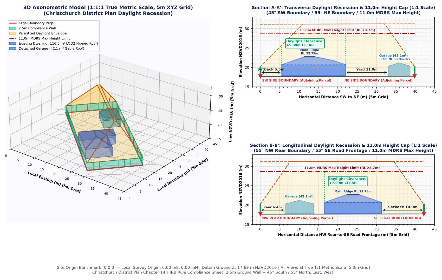
How Ground Spatial Formats Data for Seamless Import
When Ground Spatial processes raw drone scans into client deliverables, we run an automated coordinate translation before compiling the deliverable:
- We select an authoritative legal boundary peg (or site corner) as the Local Project Base Point (PBP).
- We generate a translation header inside the exported file (.E57, .RCP, or 3D DXF) storing the exact delta:
ΔX = -1,568,400.000m • ΔY = -5,184,800.000m
- All cloud points inside the file are shifted into local space relative to (0,0,0), keeping coordinate values under 100 meters.
- We provide the exact Easting, Northing, and Grid Bearing in the delivery handover sheet so your BIM manager can key it directly into Revit's Survey Point.
This allows your draughtspeople to model at (0,0,0) with sub-millimeter precision, while every export to civil consultants (LandXML, IFC, or DWG) exports back to authoritative NZTM2000.
3. The Vertical Datum Trap: Ellipsoidal vs. Orthometric NZVD2016
Vertical errors are even more common than horizontal drift.
Drones equipped with RTK GNSS measure height relative to the mathematical GPS ellipsoid (GRS80/WGS84). However, water flows according to gravity, not mathematical ellipsoids. In New Zealand, legal levels and council drainage inverts are referenced to New Zealand Vertical Datum 2016 (NZVD2016) or the historical Lyttelton 1937 datum.
In Christchurch, the separation between the GPS ellipsoid height ($h$) and the true orthometric height ($H$) is roughly +18.5 to +20.2 meters.
Ground Spatial applies the official LINZ NZGeoid2016 gravitational correction grid during point cloud post-processing, ensuring all delivered 3D CAD meshes and 0.25m bare-earth contours match council invert levels.
4. Decimation & Point Cloud Classification: Keeping File Sizes Usable
A standard 15-minute drone flight over an 800m² residential parcel produces between 30 and 60 million points. Attempting to navigate that density in Revit or ArchiCAD on an office laptop causes sluggish pan/orbit performance.
To keep models responsive without losing vital architectural details, we pass point clouds through automated ASPRS classification and spatial decimation:
- Class 2 (Bare Ground): Vegetation, lawn clippings, parked cars, and temporary site debris are filtered out. Only true bare earth remains.
- Class 6 (Building Rooftops & Walls): Isolated to provide existing structure geometry and eaves heights.
- Class 5 (High Vegetation Canopy): Retained on a separate layer for tree Root Protection Zone (RPZ) and daylight shadow modeling.
- Voxel Grid Decimation: Points across planar surfaces (driveways, lawns) are thinned to an efficient 50mm grid, while high-curvature feature lines (kerbs, boundary fences, building ridges) retain maximum resolution.
This reduces typical file size from 4.2 GB down to under 250 MB. The file loads in 3 seconds in Autodesk Recap, Revit, or ArchiCAD.
5. Step-by-Step Revit Import Checklist for NZ Projects
When importing Ground Spatial deliverables into Autodesk Revit:
- Open Project Site Plan View: Ensure both the Project Base Point and Survey Point are set to visible in your Visibility/Graphics Overrides.
- Insert Point Cloud: Go to Insert > Point Cloud. Select the Ground Spatial
.RCPor.E57file. - Positioning Option: Select "Origin to Internal Origin" (since the offset has already been pre-configured).
- Set Survey Point Coordinates: Unclip the Revit Survey Point, enter the Easting and Northing values from your Ground Spatial Handover Sheet, and re-clip it.
- Verify Against Cadastral Overlay: Link our 2D/3D Cadastral DXF. Boundaries, building lines, and contours will snap together with zero coordinate drift.